falconskytechpk.com

โ† Back to Tools

All Kind of Programmers

Programmers for reading and writing receiver chips: details, software screenshots, pictures and downloads.

1 RT809H Universal Programmer

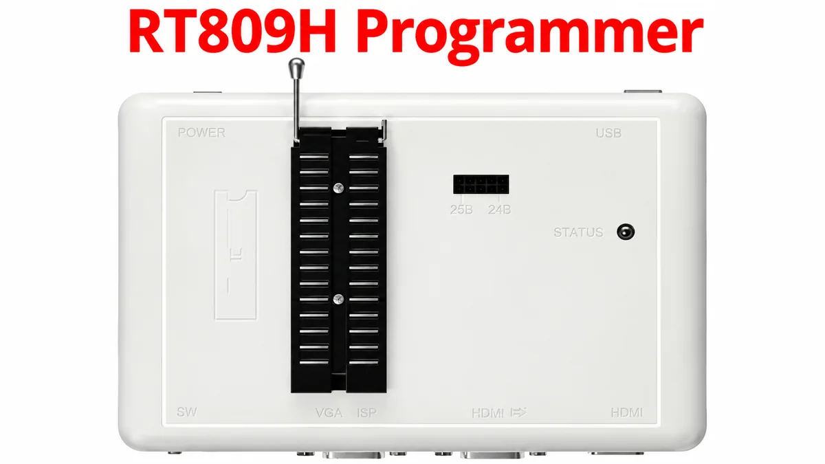
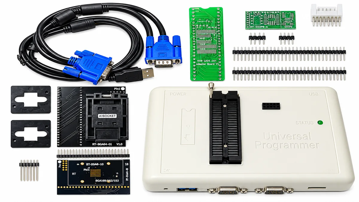
๐Ÿ”ง The RT809H is a high-speed universal EMMC-NAND flash and serial ISP programmer built for hardware repair technicians, embedded engineers and firmware specialists. You can program chips offline in its 48-pin ZIF socket, or online (ISP) through VGA, HDMI and the dedicated ISP headers. That lets you read and write firmware on LCD/LED TVs, satellite receivers, laptop motherboards (EC/BIOS), car navigation systems and set-top boxes without desoldering the chip.

๐Ÿ“– Read more โ–พโ–ด Read less
๐Ÿ”Œ 48-pin ZIF socket โšก USB 2.0, up to 25 MB/s ๐Ÿ’ฝ Software: 20240619

๐Ÿš€ Key Technical Features & Capabilities

  • ๐Ÿงฒ 48-pin universal ZIF socket: automatic chip detection and intelligent pin placement for DIP, SOP, TSOP and BGA adapters, with no manual pin-mapping.
  • โšก High-speed USB 2.0: read and write speeds of up to 25 MB/s, with WHQL-certified Windows drivers.
  • ๐Ÿง  Extensive chip support: EMMC, EMCP, SPI NOR flash, parallel NOR/NAND flash (up to 64GB), EEPROM (24/25/93 series), MCU and laptop EC chips (IT8, KB90, NPCE, MEC16 series).
  • ๐Ÿ“บ VGA & HDMI ISP ports: read and flash LCD/LED TV mainboards directly through the VGA or HDMI port, without opening the casing.
  • ๐Ÿ’พ Offline & online EMMC modes: 1-bit flying-line ISP, 4-bit/8-bit high-speed BGA socket reading and writing, and full access to the BOOT, USER, RPMB and GPP partitions.
  • ๐Ÿฉบ Self-test & diagnostics: built-in hardware self-test and serial print terminal monitoring for live board debugging.

๐Ÿงญ Hardware Ports & Interface Layout

  • ๐Ÿ”’ 48-pin ZIF locking socket: the main universal socket for DIP chips or adapter boards (SOP8, TSOP48, BGA64/169). Always align Pin 1 with the socket diagram.
  • ๐Ÿ”— 25B / 24B ISP header (10-pin IDC): the dedicated port for SPI (25-series) and I2C (24-series) in-circuit programming and flying-line connections.
  • ๐Ÿ–ฅ๏ธ VGA ISP & VGA IN ports: used to flash LCD/LED TV boards over a VGA cable and to pass through diagnostic display signals.
  • ๐Ÿ“ก HDMI ISP port: a digital interface for direct ISP communication with compatible smart TV boards.
  • ๐Ÿ”Œ USB 2.0 & external DC jack (9Vโ€“12V): connects to the PC for data and power. Use the external DC supply when programming high-capacity NAND/EMMC chips if USB power is not enough.
  • ๐Ÿ’ก STATUS LED: shows power, active read/write operations and connection readiness.

๐Ÿ› ๏ธ Software Installation & Setup

  1. ๐Ÿ“ฅ Download the official software. Download the latest RT809H software installer package from the official iFix / RT809 repository and extract the ZIP archive.
  2. ๐Ÿ›ก๏ธ Install the software before connecting the hardware. Run the setup as Administrator and finish the installation wizard. Keep the RT809H unplugged until the software and USB drivers have finished installing.
  3. ๐Ÿงฉ Install the USB drivers. When asked during setup, click OK to install the WHQL-certified USB hardware drivers.
  4. ๐Ÿ”Œ Connect the programmer. Plug the RT809H into a USB 2.0 port with the original USB cable. Avoid unpowered USB hubs and unstable front-panel USB 3.0 ports.
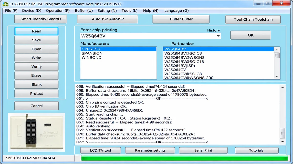
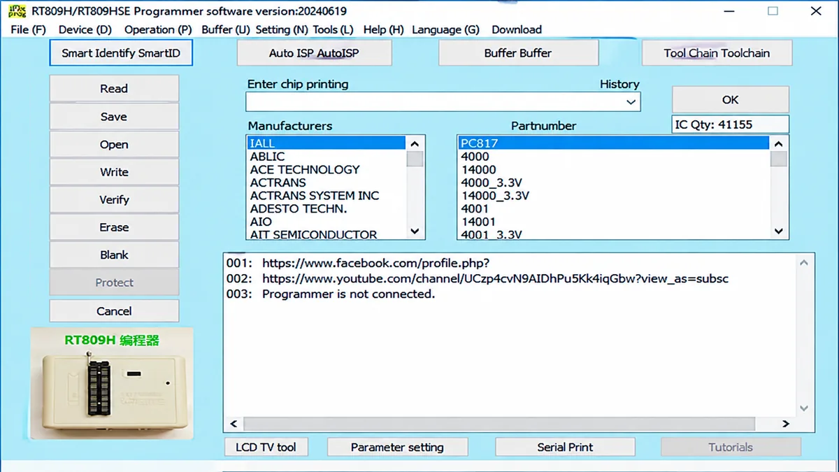
  5. โœ… Verify the connection. Open the RT809H Serial ISP Programmer software. The bottom status bar and log window should show the device serial number (for example SN:20190114โ€ฆ) instead of "Programmer is not connected."

๐Ÿ“– Method A: Reading & Backing Up a Chip (ZIF Socket / Adapter)

  1. ๐Ÿงท Insert the chip. Place the IC (for example a W25Q64BV SPI flash) into the right adapter (such as RT-SOP8-A), lock it into the 48-pin ZIF socket with Pin 1 aligned correctly, and pull the locking lever down.
  2. ๐Ÿ”Ž Identify the chip. Click Smart Identify (SmartID) at the top left of the software. It will detect the manufacturer, part number and chip ID automatically. Or type the chip number into the "Enter chip printing" box and click OK.
  3. ๐Ÿ“ค Read the firmware. Click Read. The log window shows the pin contact check, chip ID confirmation and reading progress.
  4. ๐Ÿ’พ Save the backup. When the log shows Read successful and Auto verifying... OK, click Save to store a .BIN backup file on your computer.

โœ๏ธ Method B: Erasing & Writing (Flashing) Firmware

  1. ๐Ÿ“‚ Load the firmware file. Click Open and choose the verified .BIN or .HEX firmware file you want to flash.
  2. ๐Ÿงน Erase and blank check (optional/auto). Click Erase to clear the existing data, then Blank to confirm the memory is completely empty.
  3. ๐Ÿ“ฅ Write the data. Click Write. The programmer flashes the buffer to the chip and runs a verification pass automatically.
  4. ๐ŸŽ‰ Confirm completion. Wait until the progress bar turns solid green and the log shows Verification successful before lifting the ZIF lever to remove the chip.
โš ๏ธ Troubleshooting Common Issues

  • ๐Ÿ”Œ "Programmer is not connected": plug the USB cable directly into a rear motherboard USB 2.0 port. Open Windows Device Manager and check that the RT809H driver is listed with no yellow warning icon.
  • ๐Ÿฆต Chip pin contact error: clean the IC legs with isopropyl alcohol, check the adapter orientation and reseat the chip firmly in the socket.
  • โŒ Verification failed during write: lower the programming speed in Setting, connect a 9Vโ€“12V external DC power adapter to the programmer, or check whether the chip's Protect (write-protection) status register is enabled.
ProgrammerDownloads
RT809H Universal Programmer โ€ฆ โฌ‡ Download

2 CH341A USB Flash ROM Programmer

๐Ÿ’พ The CH341A is an affordable and very versatile USB bus conversion chip and programmer. Technicians, hobbyists and engineers use it to read, write and repair SPI flash memory chips (such as the 24 EEPROM and 25 SPI flash series). It is commonly used to flash BIOS chips on motherboards, and to repair satellite receivers, routers, LCD/LED TVs and graphics cards.

๐Ÿ“– Read more โ–พโ–ด Read less
๐Ÿ’พ 24 EEPROM & 25 SPI flash ๐Ÿ”Œ USB, 3.3V / 5V ๐Ÿงท Jumper on Pin 1 & 2

๐Ÿงฉ How the CH341A Programmer Works

The CH341A hardware is a bridge between your computer's USB port and the serial protocols of memory chips:

  • ๐Ÿ”„ Protocol conversion: it translates USB data packets from the PC into SPI (Serial Peripheral Interface), I2C or UART protocols that flash memory chips understand.
  • ๐Ÿ”‹ Power & logic regulation: the board supplies the operating voltage (typically 3.3V or 5V) that powers the target IC during reading and writing.
  • ๐Ÿ–ฅ๏ธ Software interface: companion software (such as CH341A Programmer or AsProgrammer) lets you dump existing firmware, erase sectors, write new code and verify the data block by block.

โš™๏ธ Hardware Setup & Jumper Configuration (Crucial Step)

Before connecting the CH341A to your computer or to a chip, set the jumper correctly:

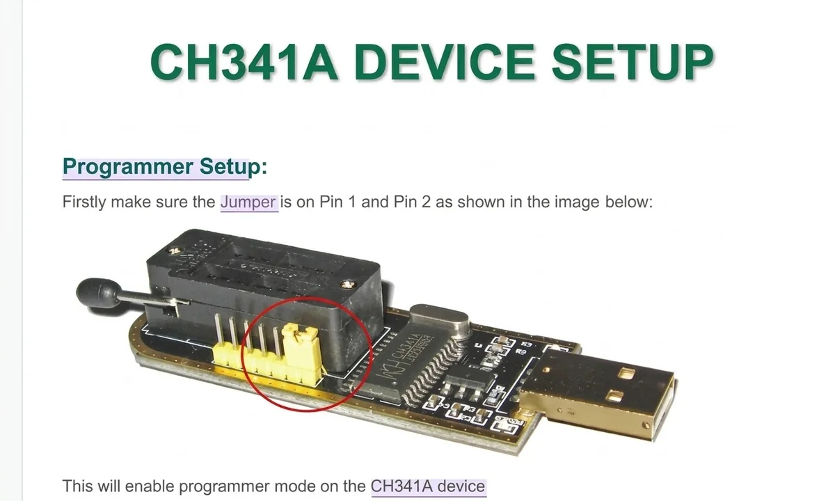
  • ๐Ÿงท Programmer mode: place the yellow jumper across Pin 1 and Pin 2, as in the setup picture, to enable SPI/I2C programmer mode. On pins 2-3 the device switches to serial/parallel printer port mode.
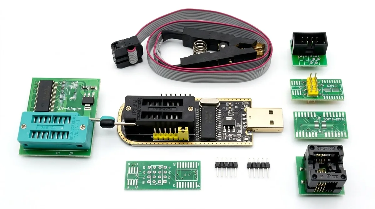
  • ๐Ÿ”’ Socket & clips: mount chips directly in the on-board 16/24/25 ZIF socket, use SOP8/SOP16 breakout adapter boards, or attach a Pomona/SOIC8 test clip to flash a chip on the circuit board without desoldering.

๐Ÿ› ๏ธ Step 1 & 2: Install Drivers, Connect and Insert the Chip

  1. ๐Ÿ“ฅ Download. Get the CH341SER USB driver and the CH341A programmer software package.
  2. ๐Ÿ›ก๏ธ Install. Install the driver, then run the software executable as Administrator.
  3. ๐Ÿ”Œ Connect the programmer. Plug the CH341A into a free USB port on your PC.
  4. ๐Ÿงท Insert the chip. Place your target chip (for example Winbond W25Q64BV) in the ZIF socket with Pin 1 aligned to the socket marking, and lock the lever. Or connect the SOIC8 clip to the chip on the motherboard, matching the Pin 1 red wire to Pin 1 on the clip adapter.

๐Ÿ“– Step 3: Detect and Read the Firmware (Backup)

  1. ๐Ÿš€ Launch the CH341A software.
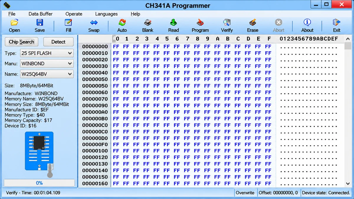
  2. ๐Ÿ”Ž Detect the chip. Click Detect or Chip Search so the software identifies the manufacturer and part number automatically.
  3. ๐Ÿ“ค Read. Click Read to pull the existing firmware from the chip into the software buffer.
  4. ๐Ÿ’พ Save the backup. When reading reaches 100%, click Save to store the original .BIN file on your computer.

โœ๏ธ Step 4: Erase and Write New Firmware

  1. ๐Ÿ“‚ Open the new replacement .BIN firmware file you want to flash.
  2. ๐Ÿงน Erase the old data from the chip.
  3. ๐Ÿ“ฅ Program (Write) to flash the new data onto the chip.
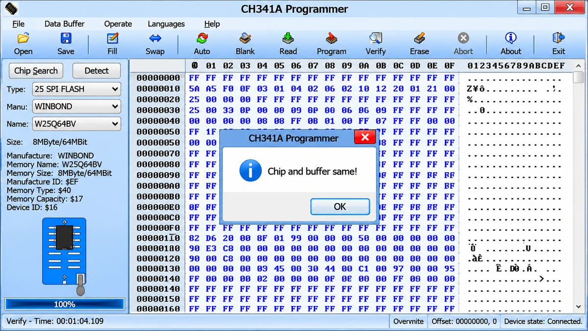
  4. โœ… Verify to confirm the chip matches the buffer completely. A prompt saying "Chip and buffer same!" means the write was successful.

โš ๏ธ Troubleshooting Common Issues

  • ๐Ÿšซ "Device Not Detected" or error states: make sure the USB driver is installed properly and the jumper is correctly seated on Pins 1 and 2.
  • ๐Ÿ” Reading shows all "FF" or "00": this means poor contact between the test clip or pins and the chip. Clean the chip pins, check the orientation, or desolder the chip and program it in the ZIF socket.
ProgrammerDownloads
CH341A USB Flash ROM Programmer โ€ฆ โฌ‡ Download